ENERGY SAVING THREE-PHASE INDUCTION MOTOR USING
FUZZY CONTROLLER
Induction motors are
extensively usedin industrial and household appliances and consume more than
50% of the total generated electrical energy. The need for energy conservation
is increasing the requirements for saving the electrical energy. Now way days
electrical power charges increase so the power saving is important in our
system.
This paper present
energy saving of three -phase induction motor, which is operated in
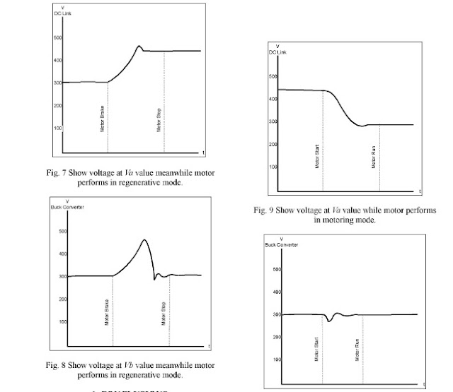
regenerating mode. In this mode, the
energy flow back into DC link voltage and causes to occur high voltage in
capacitor that may be destroy the capacitor and switching component such an
IGBT. The proposed method present connection buck converter circuit between the
rectifier diodes and the inverter, to control the voltage feeding into the
inverter by using second fuzzy controller, which provide to control the
switching component of breaking circuit. The second controller will be
synchronized with the first controller to balance the energy of the capacitor.
introduction:
Induction motors square measure extensively employed in industrial and social unit appliances and consume quite five hundredth of the entire generated current. the necessity for energy conservation is increasing the necessities for saving the current. currently means days power charges increase that the power saving is very important in our system.
This paper gift energy saving of 3 -phase induction motor, that is operated in make mode. during this mode, the energy flow back to DC link voltage associate degreed causes to occur high voltage in electrical device that will be destroy the electrical device and switch part such an IGBT. The planned methodology gift association buck device circuit between the rectifier diodes and also the electrical converter, to manage the voltage feeding into the electrical converter by victimisation second fuzzy controller, which offer to manage the switch part of breaking circuit. The second controller are going to be synchronous with the primary controller to balance the energy of the electrical device.
Induction motors square measure typically employed in process, as a result of it's easy, cheap, simple to keep up and sturdy. This paper presents energy saving of three-phase induction motor that's operated in regenerative braking. The braking effects are going to be motor modification itself to generator, that the motor can feedback some energy within the kind of current into DC link circuit [1]. during this case, if the rectifier composed with diodes, the present cannot flow backward into the facility offer. Such current can charge the capacitors, that plug with DC link circuit and inflicting the circuit is charging and increasing to high voltage till breakdown. during this paper, we are going to propose buck device to require some energy that charged the capacitors. This energy can give to payback for starter motor within the next times. The buck device provides to manage output voltage within the constant mode. switch circuit of the buck device is controlled by fuzzy system. The fuzzy system are going to be designed 2 controllers, which might be synchronous to supply the stable operation, though there's a modification within the parameters and also the motor.What Is Regeneration?
When the rotor of associate degree induction motor turns slower than the speed set by the applied frequency, the motor is reworking current into energy at the motor shaft. This method is stated as ‘motoring’. once the rotor turns quicker than the synchronous speed set by a drive output, the motor is reworking energy from the motor shaft into current. it should be a ramp to prevent, a discount in commanded speed or associate degree overhauling load that causes the shaft speed to be larger than the synchronous speed. In any case this, condition is stated as ‘regeneration”. basically, energy is born-again to current.
The case is way a similar for a DC drive and motor. the rise in DC voltage for the DC drive happens at the coil association. Some DC drives haven't solely a forward however additionally a reverse bridge. The reverse bridge permits the DC energy from the coil to be transferred to the utility line. If the DC drive has solely the forward bridge, a shunt regulator will be employed in parallel with the coil to dissipate this energy into heat. For associate degree AC drive and motor during a regenerative condition, the AC power from the motor flows backward through the electrical converter bridge diodes shown in figure one below. On most AC drives, utility power is initial born-again into DC by a diode or SCR rectifier bridge These bridges square measure terribly price effective, however solely handle power within the “motoring” direction. Since the laws of physics state that energy isn't lost or gained, this energy wants an area to travel.
If the motor is make, the DC bus voltage can increase. Unless a way of addressing the regenerative energy is provided, the drive can shield itself with a Bus Overvoltage trip, therefore stopping the regenerative condition. There square measure 3 was to handle this energy.
1) give either a “regenerative bridge converter” or a “regenerative brake” that has the power to vary the DC bus energy into mounted frequency utility power.
2) Take many drives and tie the DC bus connections along specified “regenerative” energy
from one motor / drive will be absorbed and employed by another “motoring” drive on a similar DC transit line.
3) unharness this energy within the kind of heat through a voltage regulated switch semiconductor unit and resistance. This electrical circuit is placed across the DC bus and is usually known as a “chopper” or “Dynamic Brake”. alternative names for these units square measure “Shunt regulator” and “Snubber”
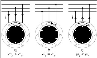
Regenerative mode:
more
than angular speed of rotor (cor ). Therefore, the result to
the revolved rotor follows rotating field that during this mode are going to be provided
power to the motor. There ar current flowing into the motor. Such current are going to be lagged
voltage and not extraordinary ninety degree of electric;thus, P = VIcos(O) could be a positive price.
In Fig. lb, once angular speed of rotor has equalised to
rotating field, there aren't manufacture the voltage induction at the rotor; then, this state no
current flows and no torsion conjointly. In Fig. 1 c, once there's a major mover to drive rotor up to the angularspeed, which is able to rotate quicker than angular speed of
the rotating field in the
meantime it provides power to motor. That
causes to rotor and rotating field ar reversed the rotating direction fromdextrorotatory to
counter dextrorotatory.
Buck device Operation:
A power convertor uses semiconductor devices to rework power from one type (DC or AC) into another type (DC or AC). It accomplishes this by inflicting the circuit topology to vary by virtue of turning ON and OFF the semiconductor devices.
A buck device could be a specific style of dc-dc power convertor whose goal is to with efficiencystep down DC voltage to a lower level with negligible ripple. sensible applications area unit illustrated in Figure one.1 where, for instance, a buck chopper may interface between the variable output voltage of a galvanic battery and a sensitive piece of natural philosophy like a chip.
usually the buck device employs feedback to control the output voltage within the presence of load changes. This improvement in performance over voltage dividers and regulators comes at the price ofextra parts and quality.
In the remainder of this give, we'll examine the characteristics of the buck chopper and derive relationships and tools necessary to properly specify the parts needed to implement a desired style
From the
relative speed principle, instead, the current will flow into the motor; it
turns to flow out from the motor to inverter. This principle is used for
breaking the inverter by providing diodes to connect inverse-parallel with
switching components of the inverter to take the current flow back from the
motor meanwhile it be a generator mode. This state will occur when reduces the
frequency of the inverter, which has an effect to angular velocity of the
rotating field, co, on the stator of the motor. However, the angular velocity
of the rotor cannot reduce suddenly. Because of the rotor remains rotate from
the momentum effect, this causes of the state that turns the motor to generator
and generates the feedback current passing the diodes to DC link as seen from
Fig. 2
Mathematical model and designing of buck converter:
The Buck
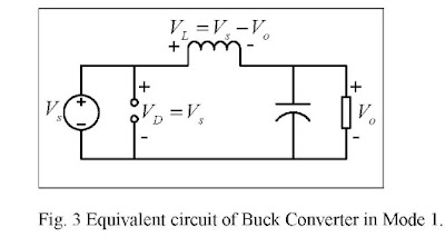
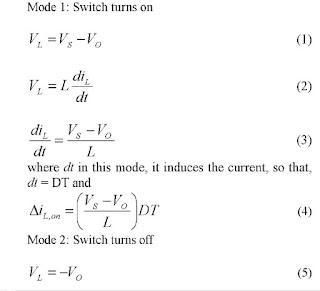
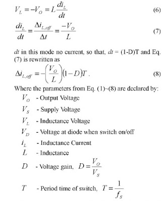
converter is modelled using the following equations. Mode 1 happens when IGBT
switching is turned ON and Mode 2 occurs when the IGBT switching is turned OFF.
The equivalent circuit of Mode 1 is given in Fig. 3, and Fig. 4 illustrates the
equivalent circuit of Mode 2
Fig 4. Equivalent circuit of Buck Converter in Mode 2. Mode 1: Switch turns on
Buck converter is designed with the selected
specifications that suitable for the selected motor. For the assumed
specification, the components were designed and the selected components are as
given in the Table 1
Fuzzy controller:
Fuzzy logic
controller is derived from fuzzy set theory, which was proposed by Zadeh in
1965. In fuzzy set theory, the transition between membership and
Non-membership
can be vague and ambiguous, making it useful for approximate systems.
Fuzzy Logic
controller is an attractive choice when precise mathematical formulations are
not possible.
Other advantages
of the fuzzy logic controller are:
1. It can work
with less precise inputs.
2. It does not
need fast processors.
3. It needs less
data storage in the form of membership functions and rules than that of
conventional look up table for nonlinear controllers.
4. It is more
robust than other non-linear controllers.
Fuzzy logic uses
linguistic variables instead of numerical variables. The process of converting
a numerical variable (real number or crisp variables) in to a linguistic
variable (fuzzy number) is called fuzzification.
Fig. 5 illustrates the
circuit of the proposed method, which the buck converter is managed by fuzzy
controller.
In our fuzzy controller,
the error of Vb, change in error of Vb and Va are fuzzified. Five linguistic
variables using triangular membership function are used and shown in Fig 6.
BASICS
OF FUZZY LOGIC CONTROLLERS
Fuzzy logic control is a new
addition to control theory. Its design philosophy deviates from all the previous
methods by accommodating expert knowledge in controller design. FLC is one of
the most successful applications of, fuzzy set theory. Its major features are
the use of linguistic variables rather than numerical variables [5]. Linguistic
variables, defined as variables whose values are sentences in a natural
language (such as small and large), may be represented by fuzzy sets. FLC’s are
an attractive choice when precise mathematical formulations are not possible.
The general structure of an FLC
is represented in Fig. 1 and comprises four principal components:
1) a fuzzification interface
which converts input data into suitable linguistic values;
2) a knowledgebase which consists of a data
base with the necessary linguistic definitions
and control rule set;
3) a decision making logic which,
simulating a human decision process, infers the fuzzy control action from the
knowledge of the control rules and the linguistic variable definitions; 4) a defuzzification interface which yields a
nonfuzzy control action from an inferred fuzzy control action.
Design of fuzzy logic or rule
based non-linear controller is easier since its control function is
described by using fuzzy sets and
if-then predefined rules rather than cumbersome mathematical equations or
larger look-up tables; it will greatly reduce the development cost and time and
needs less data storage in the form of membership functions and rules. It is adaptive
in nature and can also exhibit increased reliability, robustness in the face of
changing circuit parameters, saturation effects and external disturbances and
so on.
Fuzzification
The first step in the design of a
fuzzy logic controller is to define membership functions for the
inputs. Seven fuzzy levels or
sets are chosen and defined by the following library of fuzzy-set
values for the error e and
change in error ce:
Fig. 3. Membership functions for e
and ce.
They are as follows
NB negative big;
NM negative medium;
NS negative small;
ZE zero equal;
PS positive small;
PM positive medium;
PB positive big.
The number of fuzzy levels is not
fixed and depends on the input resolution needed in an application. The larger
the number of fuzzy levels, the higher is the input resolution. The fuzzy controller
utilizes triangular membership functions on the controller input.
The triangular membership
function is chosen due to its simplicity. For a given crisp input, fuzzifier
finds the degree of membership in every linguistic variable. Since there are
only two overlapping memberships in this specific case, all linguistic
variables except two will have zero membership
Fig. 4. Membership
functions of the input linguistic variables
Decision making
with the fuzzy controllers will operate with the rule-base as shown in Table 2.
If error of Vb is Ai, and change in error of Vb is Bi and Va is
positive then
output is Ci. Here, the if-part of the rule is called the rule-antecedent,
which is a description of a process state in term of a logical combination of
atomic fuzzy propositions. The then-part of rule-base system is called "consequent",
which is an output of the fuzzy system. Therefore from Table 2, the fuzzy
rule-base can construct as: If error of Vb is NS, and change in error of Vb is
NS, and Va is positive then output is NS.
Experimentation
results:
This paper used
to three phase induction motor using table 3
Conclusion:
This paper is shown that
the connecting of buck converter circuit for managing power that flowing back
at the same time with the motor is performed in regenerative mode. The power management
is performed by fuzzy controller to balance switching component, which will
operate the voltage of capacitor and provide the energy to the inverter. This
mechanism will protect inverter switching. However this method was designed
capacitor to endurance with the voltage of the circuit that will flow back also.
Advantages:
1. It can work with less
precise inputs.
2. It does not need fast
processors.
3. It needs less data
storage in the form of membership functions and rules than that of conventional
look up table for nonlinear controllers.
4. It is more robust than
other non-linear controllers.
Fuzzy logic uses
linguistic variables instead of numerical variables. The process of converting
a numerical variable (real number or crisp variables) in to a linguistic
variable (fuzzy number) is called fuzzification.
References:
[1] B.
Piepenbreier and L. Sack, "Regenerative drive converter with
Line-Frequency switched rectifier and without DC link components", 35h
Annual IEEE Power Electronics Specialists Conference, pp. 3917-3923, 2004.
[2] Kumpon Sirichanpong, 1 Phase ACIDC
bidirectional power flow switched mode converter for 3 phase inverter fed
induction motor drives,
Electrical
Engineering, School of graduate, King Mongkut's Institute of Technology
Ladkrabang, Thailand, 2002.
[3] N. S. Kumar,
V. Sadasivam, and K. Prema "Design and Simulation of Fuzzy Controller for
Closed Loop Control of chopper fed Embedded DC drives", IEEE Power System
Technology,





Comments
Post a Comment